Difference between revisions of "Example: Absolute Binding Affinity"
m |
|||
| (12 intermediate revisions by 3 users not shown) | |||
| Line 5: | Line 5: | ||
{| | {| | ||
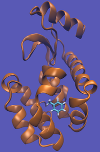
| − | | [[File:T4-Tol-Imp.png|thumb| | + | | [[File:T4-Tol-Imp.png|thumb|200px|Toluene in the complex system...]] |
| − | | [[file:Doublearrow.png| | + | | [[file:Doublearrow.png|50px]] |
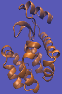
| − | | [[File:T4-Imp.png|thumb| | + | | [[File:T4-Imp.png|thumb|200px|...an unbound system...]] |
| − | | [[File:Plus_sign.jpg| | + | | [[File:Plus_sign.jpg|50px]] |
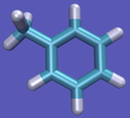
| − | | [[File:Tol-Imp.png|thumb| | + | | [[File:Tol-Imp.png|thumb|100px|...and a free toluene in solution.]] |
|} | |} | ||
| Line 20: | Line 20: | ||
This cycle is shown below where the light blue background represents the solvent environment. This can be done in either implicit or explicit solvent but is shown implicitly to avoid clutter. | This cycle is shown below where the light blue background represents the solvent environment. This can be done in either implicit or explicit solvent but is shown implicitly to avoid clutter. | ||
{| | {| | ||
| − | | align="center" style="border: 5px solid green;" | [[File:T4-Tol-Imp.png| | + | | align="center" style="border: 5px solid green;" | [[File:T4-Tol-Imp.png|120px]] |
| align="center" | | | align="center" | | ||
{| <!-- Top left-right arrow nested table "1-4" --> | {| <!-- Top left-right arrow nested table "1-4" --> | ||
| <span style="font-size:200%"> <math>\Delta A_{bind}</math></span> | | <span style="font-size:200%"> <math>\Delta A_{bind}</math></span> | ||
|- | |- | ||
| − | | [[File:Doublearrow.png| | + | | [[File:Doublearrow.png|60px]] |
|}<!-- End nested Table --> | |}<!-- End nested Table --> | ||
| align="left" | | | align="left" | | ||
{| | {| | ||
| − | | style="border: 5px solid green;" | [[File:T4-Imp.png| | + | | style="border: 5px solid green;" | [[File:T4-Imp.png|120px]] |
| − | | [[File:Plus_sign.jpg| | + | | [[File:Plus_sign.jpg|30px]] |
| − | | style="border: 5px solid orange;" | [[File:Tol-Imp.png| | + | | style="border: 5px solid orange;" | [[File:Tol-Imp.png|120px]] |
|} | |} | ||
|- | |- | ||
| Line 42: | Line 42: | ||
| align="center" | | | align="center" | | ||
{| <!-- Nested table 2-6 --> | {| <!-- Nested table 2-6 --> | ||
| − | | [[File:Doublearrowupdown.png| | + | | [[File:Doublearrowupdown.png|30px]] |
| <span style="font-size:200%"> Solvent <br/> <math>\Delta A_{coupling}</math> </span> | | <span style="font-size:200%"> Solvent <br/> <math>\Delta A_{coupling}</math> </span> | ||
|} | |} | ||
| Line 48: | Line 48: | ||
| align="center" | | | align="center" | | ||
{| style="border: 5px solid green;" | {| style="border: 5px solid green;" | ||
| − | | [[File:T4-Imp.png| | + | | [[File:T4-Imp.png|120px]] |
| − | | [[File:Plus_sign.jpg| | + | | [[File:Plus_sign.jpg|30px]] |
| − | | [[File:Tol-Nosol.png| | + | | [[File:Tol-Nosol.png|120px]] |
|} | |} | ||
| align="center" | | | align="center" | | ||
| Line 60: | Line 60: | ||
| align="center" | | | align="center" | | ||
{| | {| | ||
| − | | style="border: 5px solid green;" |[[File:T4-Imp.png| | + | | style="border: 5px solid green;" |[[File:T4-Imp.png|120px]] |
| − | | [[File:Plus_sign.jpg| | + | | [[File:Plus_sign.jpg|30px]] |
| align="center" | | | align="center" | | ||
{| style="border: 5px solid orange;" | {| style="border: 5px solid orange;" | ||
| − | | [[File:Tol-Nosol.png| | + | | [[File:Tol-Nosol.png|120px]] |
| − | | [[File:Plus_sign.jpg| | + | | [[File:Plus_sign.jpg|30px]] |
| − | | [[File:Implicit_color.png| | + | | [[File:Implicit_color.png|120px]] |
|} | |} | ||
|} | |} | ||
|} | |} | ||
| + | |||
| + | The alchemical pathway does suffer from a few problems. Firstly, as you change the interactions, the ligand has a chance of wandering off into infinity or at the least through the entirety of the simulation box; the ligand could also get stuck in different parts of the protein in the near-"ghost" states. Both of these actions can lead to significant [[Simulation_Information_Gathering#Correlation| correlation times]] and make accurate free energy calculations difficult. Furthermore, we do not collect any information about the standard state of the system (the universal constant that makes ''true'' absolute free energy calculations possible) resulting in any equilibrium constants being defined only up to the standard state. | ||
| + | |||
| + | In order to resolve these problems, one of the most standard solutions is to harmonically restrain the ghost state ligand to be in a certain location described by the geometry of the protein. If this is done, you will have to remove the harmonic restraint with the analytical correction shown below for the pulling method before making the transfer to the solvent only system. | ||
| + | |||
| + | This restraint is different from the pulling method described below though. In the pulling method, the ligand is restricted to a point in space, whereas here, the ligand is confined to a geometric point in the cavity defined by the protein, which will be as close to the average bound location as possible. Although you can get away with simple translational restrictions, there is strong evidence that computational efficiency will improve by restraining the orientational configuration of the ligand as well.{{cite|Boresh2003}}{{cite|Mobley2006}}. | ||
==[[Intermediate_States#Pulling_Methods | Pulling Pathway]]== | ==[[Intermediate_States#Pulling_Methods | Pulling Pathway]]== | ||
| + | The pulling pathway starts with the same configuration of the ligand bound to the protein. We then add a harmonic restraint to the center of mass of the ligand and move the center of the restraint away from the pocket over a series of intermediates. After the ligand is sufficiently far away, we turn off the harmonic restraints. If we are far enough away, there are effectively no interactions with the protein and ligand and the two can be treated as isolated in their own solvent boxes. | ||
| + | |||
| + | It should be noted that the above diagram is a crude representation of the pulling method and is designed to serve only as a visual cue to how the pulling method works. | ||
| + | {| | ||
| + | | align="center" style="border: 5px solid green;" | [[File:T4-Tol-Imp.png|120px]] | ||
| + | | align="center" | | ||
| + | {| <!-- Top left-right arrow nested table "1-4" --> | ||
| + | | <span style="font-size:200%"> <math>\Delta A_{bind}</math></span> | ||
| + | |- | ||
| + | | [[File:Doublearrow.png|60px]] | ||
| + | |}<!-- End nested Table --> | ||
| + | | align="left" | | ||
| + | {| | ||
| + | | style="border: 5px solid green;" | [[File:T4-Imp.png|120px]] | ||
| + | | [[File:Plus_sign.jpg|30px]] | ||
| + | | style="border: 5px solid orange;" | [[File:Tol-Imp.png|120px]] | ||
| + | |} | ||
| + | |- | ||
| + | | align="center" | | ||
| + | {| | ||
| + | | [[File:Doublearrowupdown.png|30px]] | ||
| + | | <span style="font-size:200%"> Complex <br/> <math>\Delta A_{unconstrain}</math> </span> | ||
| + | |} | ||
| + | | | ||
| + | | align="center" | | ||
| + | {| <!-- Nested table 2-6 --> | ||
| + | | [[File:Doublearrowupdown.png|20px]] | ||
| + | | <span style="font-size:200%"> Solvent <br/> <math>\Delta A_{unconstrain}</math> </span> | ||
| + | |} | ||
| + | |- | ||
| + | | align="center" style="border: 5px solid green;" | [[File:T4-Tol-Imp-Well.png|120px]] | ||
| + | | align="center" | | ||
| + | {| <!-- bottom left-right arrow nested table 3-4 --> | ||
| + | | <span style="font-size:200%"> <math>\Delta A_{pull}</math></span> | ||
| + | |- | ||
| + | | align="center" | [[File:Doublearrow.png|60px]] | ||
| + | |} | ||
| + | | align="center" style="border: 5px solid green;" | [[File:T4-Tol-Pull.gif]] | ||
| + | |} | ||
| + | |||
| + | |||
| + | Using this method does have its drawbacks as you will need a very large simulation box and the pathway the ligand should take is not always intuitive. For instance, this particular system has a burred binding site, making the path very difficult to define without running into large repulsion barriers. | ||
| + | |||
| + | ==Harmonic Restraints== | ||
| + | Although not every point in this section applies to both methods, there are enough common points to take note of. These are by no means the only restraint schemes, just some examples. | ||
| + | |||
| + | The effect of the harmonic constraint can be removed analytically by calculating | ||
| + | |||
| + | :<math>\displaystyle \Delta A_{unconstrain}^{solvent} = kT\ln\left[\frac{3}{V}\left(\frac{\pi kT}{K}\right)^{3/2}\right]</math> | ||
| + | |||
| + | where <math>K</math> is the force constant of the spring, and <math>V</math> is the volume of the reference state. The average volume per molecule for a reference concentration of <math>1 M</math> is 1.661 x 10<sup>3</sup> Å<sup>3</sup>/molecule. | ||
| + | |||
| + | It should be noted that the free state should not have the restraints and that the restraints are added along intermediaries as well. Rotational and translational degrees of freedom only need to be sampled as the restraints are turned on, instead of at every intermediate. | ||
| + | |||
| + | For translational harmonic restraints, the free energies can be computed using the following potential: | ||
| + | |||
| + | :<math>\displaystyle U(x_{cm-ligand}) = \frac{K}{2(x_{cm-ligand}-x_0)^2}</math> | ||
| + | |||
| + | where <math>x_{cm-ligand}</math> is the center of mass of the ligand, <math>x_0</math> is the anchor point, and <math>K</math> is the spring constant. Harmonic orientational restraints are placed on six degrees of freedom: one distance, two angles, and three torsions; these are determined by the location of three ligand and three protein atoms.{{cite|Boresh2003}}{{cite|Mobley2006}} | ||
| + | |||
| + | ===When should restraints be added?=== | ||
| + | In the methods discussed above, the restraints were applied as the decoupling process occurred. You could alternately apply the restraints ''before'' doing any kind of decoupling actions. This will require more intermediate states but may be more efficient in the long run since you will have shorter correlation times after the restraints are added. It is not clear which choice is the best in general. | ||
| + | |||
| + | If you turn on the restraints too quickly, you will have poor sampling of the torsion angles and thus the results will not converge to the correct results. | ||
=What are the End States?= | =What are the End States?= | ||
| − | + | Since we are exploring two possible pathways for this problem, both pathways will be explored for their end states. | |
| − | |||
| − | |||
| − | + | ==Alchemical Path End States== | |
| − | + | In the alchemical pathway as seen above, there are four stages along our thermodynamic cycle. As we saw in [[Example:_Relative_Binding_Affinity| relative binding affinity example]], we can simulate all but one of the free energy changes and calculate the rest. Since this case would need three calculations, there are two end points affiliated with each change making a total of six end states. However, recall that there is a zero change in free energy of transferring the fully non-interacting ligand from the complex to the solvent-only system; this means we only have to worry about two of the calculations with two end points each. | |
| − | + | Our first simulation (which we will call "''A-1''") will be of the ligand in the protein transitioning to the decoupled state. The starting, bound configuration is identical to the starting configuration of the [[Example:_Relative_Binding_Affinity| relative binding affinity example]]. The final state of ''A-1'' is the protein in "complex" with the decoupled ligand, of which we have two choices here as well. In either case, all ''inter''molecular interactions will be turned off so the ligand does not interact with its environment. The difference comes from how many ''intra''molecular interactions are left on. The most straightforward choice is to leave all intramolecular interactions intact, however, this may take longer to converge. The alternate choice is to turn off only nonbonded and proper torsional terms in the ligand to aid convergence. | |
| + | :'''Caution''': Do not turn off bonds, angles, or improper terms as geometric distortions could arise and cause convergence problems. | ||
| + | So long as the ligand is transferred to the solvent-only system in the same state, the overall free energy calculation should not depend on which decoupling choice you make. | ||
| + | |||
| + | The second simulation ("''A-2''") is based on the decoupling choice from ''A-1'' and will have similar methods as the [[Example: Absolute Solvation Free Energy|absolute solvation free energy]] example. The first end point of this is the decoupled ligand "ghost" in a box of the solvent. This "ghost" must have the same types of interactions as the decoupled ligand from ''A-1'' in order to have a zero free energy change for the transfer of the ligand from ''A-1'' to ''A-2''. If you had chosen to only turn off intermolecular interactions, then ''A-2'' will be identical to the [[Example: Absolute Solvation Free Energy|absolute solvation free energy]] example. Knowing the free energy of solvation in advance for your ligand may motivate you to choose this pathway over a partial intramolecular interaction pathway. | ||
| + | |||
| + | ==Pulling Path End States== | ||
| + | The pulling pathway will follow end states not seen in the [[Example:_Relative_Binding_Affinity|previous]] [[Example: Absolute Solvation Free Energy|two]] examples since we are now dealing with harmonic restraints. | ||
| + | |||
| + | The first calculation, "''P-1''", will have two end states. The first of these is identical to ''A-1'' which has the protein and ligand fully interacting in the solvated system. The second end state for ''P-1'' will be the protein and ligand with the [[#Harmonic Restraints|harmonic restraint]] placed on the ligand to restrain it geometrically. A linear activation of the harmonic terms is usually adequate. It is important to apply the harmonic restraint prior to trying to pull the ligand away from the protein to maximize [[Constructing a Pathway of Intermediate States|phase space overlap]]. | ||
| + | |||
| + | The second pulling calculation, "''P-2''", involves has two end states where one is identical to the end state of ''P-1'' with the harmonic restraint applied, and the other has the harmonic restraint "pinning" the ligand far enough away from the protein to no be considered interacting anymore. The exact distance you will need to be away from the protein is highly system depended, but some examples show you can get away with as little as 10 Å away from the nearest approach to the protein if your system does not have large charge-charge interactions between ligand and protein. It is important to note that this minimum distance is in any direction, even over periodic boundary conditions; this should make it even more apparent how large your simulation box must be for a pulling method to be accurate. | ||
| − | |||
=What are the [[Intermediate States]]?= | =What are the [[Intermediate States]]?= | ||
| − | + | This example has more atoms changing than either [[Example:_Relative_Binding_Affinity|previous]] [[Example: Absolute Solvation Free Energy|example]] and as such will need a highly efficient pathway to retain good [[Constructing a Pathway of Intermediate States|phase space overlap]]. Even though the term "alchemical" implies that the atoms are changing identity, we are still changing the nature of the molecule in the pulling methods. This means that that a large number of atoms are changing in both methods and are both subject to the same [[Intermediate_States#Rules_of_Thumb_for_Intermediate_States|best practices principals]]. | |
| − | + | The alchemical pathway has the same high efficiency pathway as the [[Example: Relative Binding Affinity| relative binding example]] in that the charges should be turned off linearly and the Lennard-Jones interactions with a [[Intermediate_States#Soft_Core_Potentials| soft core potential]]. Choosing to turn off intramolecular interactions as well is entirely your choice so long as you do the exact reverse when you turn them back on. You may consider doing this to worry less about [[Simulation_Information_Gathering#Correlation|correlation times]], however, the intramolecular motions typically have lower correlation times than the intermolecular interactions, so there may be a negligible efficiency boost. The most efficient pathway in the complex system will usually be the same for the solvent system. | |
| − | |||
| − | # | ||
| − | |||
| − | |||
| − | |||
| − | + | For the pulling method, the intermediate states should be a sequence of moving the "pinning" point of the harmonic restraint away from the starting configuration slow enough to have sufficient volume overlap with adjacent states. The exact path over which the restraint will follow is highly system depended and may take a few trials to determine the most efficient path. | |
=What [[Simulating_States_of_Interest | Simulations to Run]]?= | =What [[Simulating_States_of_Interest | Simulations to Run]]?= | ||
| − | As with all free energy methods, start by equilibrating all intermediate states. | + | As with all free energy methods, start by equilibrating all intermediate states. Everything for the alchemical procedure (and a good majority of the pulling method) follow the same notes as for the [[Example: Relative Binding Affinity#What Simulations to Run?|relative binding example's simulation section]]. Although there is some slight deviations in the exact nature of the intermediate states, the methods and considerations are the same. |
| − | + | If [[Simulation_Acceleration#Hamiltonian_Replica_Exchange|Hamiltonian exchange]] or [[Simulation_Acceleration#Other_Methods|expanded ensemble]] techniques are carried out, then the absolute binding calculations for the alchemical path may converge more quickly than the relative binding example since the ligand can diffuse more and escape traps more easily due to the reduced degree of fully interacting atoms in the intermediates. | |
| − | + | Unlike the animated picture of the pulling method shown above, you should not run your simulations in such a way that the harmonic restraint actually moves in a given simulation. Instead, each "pinning" position should be its own simulation and the simulations should run for similar times as the relative binding example to hopefully get adequate sampling at each position. | |
| − | |||
=What [[Analyzing Simulation Results|Analysis do we Perform]]?= | =What [[Analyzing Simulation Results|Analysis do we Perform]]?= | ||
| − | + | All the pitfalls here will be identical to the [[Example: Absolute Solvation Free Energy| absolute solvation example]] for ''A-2'' of the alchemical pathway and the [[Example:_Relative_Binding_Affinity|relative binding example]] for the remainder of the simulations. | |
| − | + | Verifying the pulling method will likely require visualization (as you should do with the alchemical method as well), but choice of the initial state is equally important. | |
| − | + | In general, the absolute free energy of binding is larger than the relative free energies of binding and so there is frequently far less error cancellation. This can propagate error, making it hard to detect model errors as they may be masked by either method or setup errors. | |
| − | |||
| − | + | =References= | |
| + | <references> | ||
| + | {{cite|Boresh2003|Boresch, S., Tettinger, F., Leitgeb, M., and Karplus, M. (2003) Absolute binding free energies: A quantitative approach for their calculation. ''J. Phys. Chem. A'' 107, 9535–9551.|http://www.citeulike.org/group/14929/article/9052098}} | ||
| − | + | {{cite|Mobley2006|Mobley, D. L., Chodera, J. D., and Dill, K. A. (2006) On the use of orientational restraints and symmetry corrections in alchemical free energy calculations. ''J. Chem. Phys.'' 125, 084902.|http://www.citeulike.org/group/14929/article/9052440}} | |
| − | + | </references> | |
| − | |||
| − | <references | ||
Latest revision as of 18:39, 18 June 2013
| Free Energy Fundamentals |
|---|
 |
|
Methods of Free Energy Simulations
|
| Free Energy How-to's |
|---|
 |
This example will be different still from the other two examples in that this will touch on both the pulling method and the alchemical decoupling. Either of these methods are acceptable and are the most useful for this system.
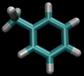
For this particular example, we will look at the absolute binding free energies of toluene in the apolar cavity of T4 Lysozyme. Furthermore, since we are also doing a solvation coupling step, the solvated environments will be visually emphasized.
What is the Thermodynamic Cycle?
For our simulation, we can use either the pulling method or the alchemical path. We will explore each one individually.
Alchemical Pathway
The alchemical cycle starts with the ligand bound to the protein to make up the complex fully interacting with the environment. We first start by decoupling the ligand from the surrounding environment, both protein and solvent. Note that we do not annihilate the ligand by turning off intramolecular interactions, just intermolecular ones. We can then transfer this "ghost" molecule from the solvent box with protein to a solvent box with no protein. This transfer has a zero free energy cost since the ligand is not interacting at all. We then recouple the ligand with its new solvent box and complete the cycle. Remember, we do not want to remove the ligand from the universe, just its interactions with the protein.
This cycle is shown below where the light blue background represents the solvent environment. This can be done in either implicit or explicit solvent but is shown implicitly to avoid clutter.
The alchemical pathway does suffer from a few problems. Firstly, as you change the interactions, the ligand has a chance of wandering off into infinity or at the least through the entirety of the simulation box; the ligand could also get stuck in different parts of the protein in the near-"ghost" states. Both of these actions can lead to significant correlation times and make accurate free energy calculations difficult. Furthermore, we do not collect any information about the standard state of the system (the universal constant that makes true absolute free energy calculations possible) resulting in any equilibrium constants being defined only up to the standard state.
In order to resolve these problems, one of the most standard solutions is to harmonically restrain the ghost state ligand to be in a certain location described by the geometry of the protein. If this is done, you will have to remove the harmonic restraint with the analytical correction shown below for the pulling method before making the transfer to the solvent only system.
This restraint is different from the pulling method described below though. In the pulling method, the ligand is restricted to a point in space, whereas here, the ligand is confined to a geometric point in the cavity defined by the protein, which will be as close to the average bound location as possible. Although you can get away with simple translational restrictions, there is strong evidence that computational efficiency will improve by restraining the orientational configuration of the ligand as well.[1][2].
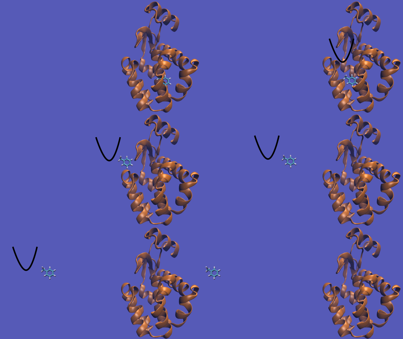
Pulling Pathway
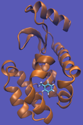
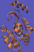
The pulling pathway starts with the same configuration of the ligand bound to the protein. We then add a harmonic restraint to the center of mass of the ligand and move the center of the restraint away from the pocket over a series of intermediates. After the ligand is sufficiently far away, we turn off the harmonic restraints. If we are far enough away, there are effectively no interactions with the protein and ligand and the two can be treated as isolated in their own solvent boxes.
It should be noted that the above diagram is a crude representation of the pulling method and is designed to serve only as a visual cue to how the pulling method works.
|
|
| |||||
|
| ||||||
|
|
|
Using this method does have its drawbacks as you will need a very large simulation box and the pathway the ligand should take is not always intuitive. For instance, this particular system has a burred binding site, making the path very difficult to define without running into large repulsion barriers.
Harmonic Restraints
Although not every point in this section applies to both methods, there are enough common points to take note of. These are by no means the only restraint schemes, just some examples.
The effect of the harmonic constraint can be removed analytically by calculating
- [math]\displaystyle{ \displaystyle \Delta A_{unconstrain}^{solvent} = kT\ln\left[\frac{3}{V}\left(\frac{\pi kT}{K}\right)^{3/2}\right] }[/math]
where [math]\displaystyle{ K }[/math] is the force constant of the spring, and [math]\displaystyle{ V }[/math] is the volume of the reference state. The average volume per molecule for a reference concentration of [math]\displaystyle{ 1 M }[/math] is 1.661 x 10³ Å3/molecule.
It should be noted that the free state should not have the restraints and that the restraints are added along intermediaries as well. Rotational and translational degrees of freedom only need to be sampled as the restraints are turned on, instead of at every intermediate.
For translational harmonic restraints, the free energies can be computed using the following potential:
- [math]\displaystyle{ \displaystyle U(x_{cm-ligand}) = \frac{K}{2(x_{cm-ligand}-x_0)^2} }[/math]
where [math]\displaystyle{ x_{cm-ligand} }[/math] is the center of mass of the ligand, [math]\displaystyle{ x_0 }[/math] is the anchor point, and [math]\displaystyle{ K }[/math] is the spring constant. Harmonic orientational restraints are placed on six degrees of freedom: one distance, two angles, and three torsions; these are determined by the location of three ligand and three protein atoms.[1][2]
When should restraints be added?
In the methods discussed above, the restraints were applied as the decoupling process occurred. You could alternately apply the restraints before doing any kind of decoupling actions. This will require more intermediate states but may be more efficient in the long run since you will have shorter correlation times after the restraints are added. It is not clear which choice is the best in general.
If you turn on the restraints too quickly, you will have poor sampling of the torsion angles and thus the results will not converge to the correct results.
What are the End States?
Since we are exploring two possible pathways for this problem, both pathways will be explored for their end states.
Alchemical Path End States
In the alchemical pathway as seen above, there are four stages along our thermodynamic cycle. As we saw in relative binding affinity example, we can simulate all but one of the free energy changes and calculate the rest. Since this case would need three calculations, there are two end points affiliated with each change making a total of six end states. However, recall that there is a zero change in free energy of transferring the fully non-interacting ligand from the complex to the solvent-only system; this means we only have to worry about two of the calculations with two end points each.
Our first simulation (which we will call "A-1") will be of the ligand in the protein transitioning to the decoupled state. The starting, bound configuration is identical to the starting configuration of the relative binding affinity example. The final state of A-1 is the protein in "complex" with the decoupled ligand, of which we have two choices here as well. In either case, all intermolecular interactions will be turned off so the ligand does not interact with its environment. The difference comes from how many intramolecular interactions are left on. The most straightforward choice is to leave all intramolecular interactions intact, however, this may take longer to converge. The alternate choice is to turn off only nonbonded and proper torsional terms in the ligand to aid convergence.
- Caution: Do not turn off bonds, angles, or improper terms as geometric distortions could arise and cause convergence problems.
So long as the ligand is transferred to the solvent-only system in the same state, the overall free energy calculation should not depend on which decoupling choice you make.
The second simulation ("A-2") is based on the decoupling choice from A-1 and will have similar methods as the absolute solvation free energy example. The first end point of this is the decoupled ligand "ghost" in a box of the solvent. This "ghost" must have the same types of interactions as the decoupled ligand from A-1 in order to have a zero free energy change for the transfer of the ligand from A-1 to A-2. If you had chosen to only turn off intermolecular interactions, then A-2 will be identical to the absolute solvation free energy example. Knowing the free energy of solvation in advance for your ligand may motivate you to choose this pathway over a partial intramolecular interaction pathway.
Pulling Path End States
The pulling pathway will follow end states not seen in the previous two examples since we are now dealing with harmonic restraints.
The first calculation, "P-1", will have two end states. The first of these is identical to A-1 which has the protein and ligand fully interacting in the solvated system. The second end state for P-1 will be the protein and ligand with the harmonic restraint placed on the ligand to restrain it geometrically. A linear activation of the harmonic terms is usually adequate. It is important to apply the harmonic restraint prior to trying to pull the ligand away from the protein to maximize phase space overlap.
The second pulling calculation, "P-2", involves has two end states where one is identical to the end state of P-1 with the harmonic restraint applied, and the other has the harmonic restraint "pinning" the ligand far enough away from the protein to no be considered interacting anymore. The exact distance you will need to be away from the protein is highly system depended, but some examples show you can get away with as little as 10 Å away from the nearest approach to the protein if your system does not have large charge-charge interactions between ligand and protein. It is important to note that this minimum distance is in any direction, even over periodic boundary conditions; this should make it even more apparent how large your simulation box must be for a pulling method to be accurate.
What are the Intermediate States?
This example has more atoms changing than either previous example and as such will need a highly efficient pathway to retain good phase space overlap. Even though the term "alchemical" implies that the atoms are changing identity, we are still changing the nature of the molecule in the pulling methods. This means that that a large number of atoms are changing in both methods and are both subject to the same best practices principals.
The alchemical pathway has the same high efficiency pathway as the relative binding example in that the charges should be turned off linearly and the Lennard-Jones interactions with a soft core potential. Choosing to turn off intramolecular interactions as well is entirely your choice so long as you do the exact reverse when you turn them back on. You may consider doing this to worry less about correlation times, however, the intramolecular motions typically have lower correlation times than the intermolecular interactions, so there may be a negligible efficiency boost. The most efficient pathway in the complex system will usually be the same for the solvent system.
For the pulling method, the intermediate states should be a sequence of moving the "pinning" point of the harmonic restraint away from the starting configuration slow enough to have sufficient volume overlap with adjacent states. The exact path over which the restraint will follow is highly system depended and may take a few trials to determine the most efficient path.
What Simulations to Run?
As with all free energy methods, start by equilibrating all intermediate states. Everything for the alchemical procedure (and a good majority of the pulling method) follow the same notes as for the relative binding example's simulation section. Although there is some slight deviations in the exact nature of the intermediate states, the methods and considerations are the same.
If Hamiltonian exchange or expanded ensemble techniques are carried out, then the absolute binding calculations for the alchemical path may converge more quickly than the relative binding example since the ligand can diffuse more and escape traps more easily due to the reduced degree of fully interacting atoms in the intermediates.
Unlike the animated picture of the pulling method shown above, you should not run your simulations in such a way that the harmonic restraint actually moves in a given simulation. Instead, each "pinning" position should be its own simulation and the simulations should run for similar times as the relative binding example to hopefully get adequate sampling at each position.
What Analysis do we Perform?
All the pitfalls here will be identical to the absolute solvation example for A-2 of the alchemical pathway and the relative binding example for the remainder of the simulations.
Verifying the pulling method will likely require visualization (as you should do with the alchemical method as well), but choice of the initial state is equally important.
In general, the absolute free energy of binding is larger than the relative free energies of binding and so there is frequently far less error cancellation. This can propagate error, making it hard to detect model errors as they may be masked by either method or setup errors.
References
- ↑ 1.0 1.1 Boresch, S., Tettinger, F., Leitgeb, M., and Karplus, M. (2003) Absolute binding free energies: A quantitative approach for their calculation. J. Phys. Chem. A 107, 9535–9551. - Find at Cite-U-Like
- ↑ 2.0 2.1 Mobley, D. L., Chodera, J. D., and Dill, K. A. (2006) On the use of orientational restraints and symmetry corrections in alchemical free energy calculations. J. Chem. Phys. 125, 084902. - Find at Cite-U-Like
